

VLSI (Very Large Scale Integration)
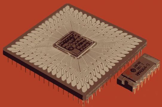
1. VLSI: Very-large-scale integration (VLSI) is the process of creating integrated circuits by combining thousands of transistor-based circuits into a single chip. VLSI began in the 1970s when complex semiconductor and communication technologies were being developed. The microprocessor is a VLSI device. The term is no longer as common as it once was, as chips have increased in complexity into the hundreds of millions of transistors. The links below are useful to know more about VLSI design.
VLSI Circuit Design Lecture Slides
Microelectronic Devices and circuits Lecture notes
CAD for VLSI
A full custom ASIC chip is the most costly, and like standard cell ASICs, use a custom-designed mask for every layer in the chip. Unlike standard cells, designers of a full custom device have total control over the size of every transistor forming every logic gate, so they can "fine tune" each gate for optimum performance. Thus, a full custom ASIC performs electronic operations as fast as it is possible to do so, providing that the circuit design is efficiently architected.
To know more visit the link below.
Analog Design - For Analog design visit this site
The designers of Verilog wanted a language with syntax similar to the C programming language so that it would be familiar to engineers and readily accepted. The language is case-sensitive, has a preprocessor like C, and the major control flow keywords, such as "if" and "while", are similar. The formatting mechanism in the printing routines and language operators and their precedence are also similar.
The link below has tutorial for verilog. Go through it to gain some knowledge on verilog programming.
4. SystemVerilog is a combined Hardware Description Language and Hardware Verification Language based on extensions to Verilog. The link below consists of tutorials for learning SystemVerilog.
Below are the tutorial links for learning Specman.
Specman Tutorial
Specman Verification


0 comments:
Post a Comment